What Is a High Torque BLDC Motor?

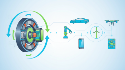
A High Torque Bldc Motor is built to deliver strong rotational force from a compact electrical package. Unlike a brushed motor, it uses electronic commutation instead of physical brushes. This design can reduce wear, improve efficiency, and support precise speed control. It is commonly used in electric vehicles, industrial robots, conveyors, pumps, and automated machinery.

Torque matters most when a machine starts, accelerates, or carries a heavy load. Professor R. Krishnan, a respected motor-drive researcher and author, explains, “The torque developed by a motor is proportional to the product of the flux and the armature current.” That principle remains practical today. More current can produce more torque, but heat rises quickly. Cooling is essential. So is correct controller tuning. A larger motor is not always better. Sometimes, it only adds weight, cost, and wasted energy.

This guide examines how a High Torque Bldc Motor produces force, how its magnets and windings interact, and how engineers select suitable specifications. We will consider torque density, continuous torque, peak torque, voltage, current, thermal limits, and feedback systems. Real applications rarely match laboratory conditions. Bearings wear. Loads change. Cables lose energy. Even published ratings can mislead when testing methods differ. That uncertainty deserves attention. A reliable selection process must examine the complete drive system, not the motor alone. The goal is practical performance: controlled acceleration, stable operation, and dependable torque under real working conditions.
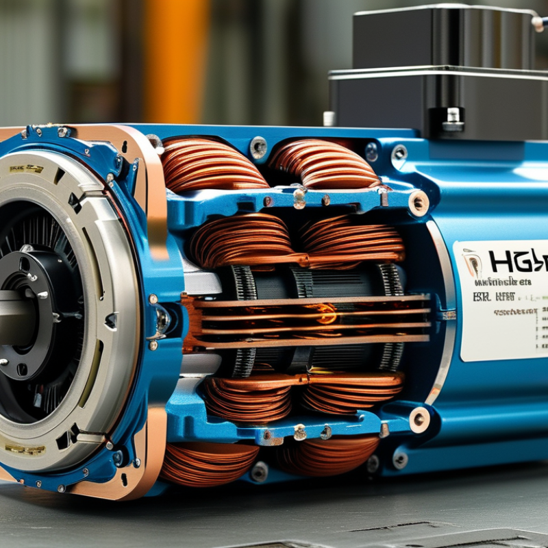
What Is a High Torque BLDC Motor?

Definition and Core Characteristics of a High Torque BLDC Motor

What Is a High Torque BLDC Motor?

A high torque BLDC motor is a brushless DC motor designed to produce strong rotational force. It uses permanent magnets, stator windings, and electronic commutation instead of mechanical brushes. This structure reduces brush wear and supports accurate speed control. Its key feature is torque density: more usable force from a compact motor. High torque performance usually comes from a larger torque constant, sufficient phase current, and effective heat removal. Low-speed torque is especially valuable in robotic joints, conveyors, electric actuators, and precision positioning systems.

However, “high torque” should never be judged by one number. A motor may deliver impressive peak torque for a few seconds but provide much less continuous torque. During practical testing, engineers should check winding temperature, supply voltage, controller limits, and operating speed. Mounting also matters. A poorly aligned shaft can create vibration, noise, and premature bearing damage. A gearbox may increase output torque, but it does not make the motor itself stronger. This distinction is often missed.

Tips: Compare continuous and peak torque separately. Ask for torque-speed curves, not only marketing values. Check thermal ratings under real load conditions. Leave cooling space around the housing. I once saw a compact design prioritize peak output and overlook heat buildup. It worked briefly, then performance declined. That result deserves review, not excuses.
How High Torque BLDC Motors Generate Rotational Force

A high torque BLDC motor creates rotational force by controlling current through stationary stator windings. Permanent magnets on the rotor respond to this changing magnetic field. Electronic sensors or sensorless controls adjust the switching sequence, keeping the magnetic fields correctly aligned. The basic relationship is simple: torque equals torque constant multiplied by current. More current usually produces more torque.

The details matter.

A larger rotor radius increases leverage at the shaft. Stronger magnets raise magnetic flux, while thicker copper windings handle higher current. However, resistance converts current into heat. Poor cooling can reduce torque quickly, even when the motor looks powerful on paper. This is where practical testing becomes essential. A motor may deliver high peak torque for seconds, but continuous torque is often much lower.

The U.S. Department of Energy’s Motor Systems Market Assessment identifies motor-driven systems as major industrial electricity users, making efficiency and thermal control important design concerns. The International Energy Agency reported nearly 14 million electric car sales in 2023, increasing demand for compact, efficient traction motors. In real applications, engineers measure torque at specific speeds, temperatures, and duty cycles. That approach prevents misleading comparisons. A high torque rating alone is not enough. Gear reduction, controller limits, rotor balance, and cooling conditions can change the final result. Sensorless control can also lose precision at very low speed. This remains a practical weakness.

Key Components and Motor Design Factors

What Is a High Torque BLDC Motor?

A high torque BLDC motor produces strong rotational force without using mechanical brushes. Its performance depends on coordinated electrical, magnetic, and mechanical parts. The stator contains copper windings that create a rotating magnetic field. The rotor carries permanent magnets and follows that field with precise timing. Hall sensors or sensorless control estimate rotor position for accurate commutation. Small errors matter.

Key components include the winding layout, magnet shape, shaft, bearings, position sensors, and electronic controller. More copper usually supports higher current, but it also creates heat. Strong magnets can increase torque density, although excessive magnetic force may raise manufacturing difficulty. The controller must deliver current smoothly and respond quickly during sudden loads. A weak control system can make an excellent motor feel unstable. During bench testing, temperature near the winding surface deserves close attention.

Motor design also depends on duty cycle, speed range, rotor inertia, cooling, and available space. A wide air gap may simplify assembly, but it can reduce magnetic efficiency. A narrow air gap improves performance, yet it demands tighter manufacturing accuracy. The shaft must resist twisting under repeated starts, not only peak torque. More torque is not always better. An oversized motor can waste energy and respond slowly. Early designs often overlook heat paths, and that mistake can limit real-world reliability.

What Is a High Torque BLDC Motor? - Key Components and Motor Design Factors

Category Key Component or Design Factor Function in a High-Torque BLDC Motor Typical Engineering Data or Range Main Design Considerations
Motor Definition High-Torque BLDC Motor Produces strong rotational force without mechanical brushes by using electronically commutated windings. Torque is commonly expressed as N·m; continuous torque depends on cooling, winding temperature, speed, and duty cycle. A high torque rating must be evaluated together with continuous torque, peak torque, speed, thermal limits, and operating time.
Electromagnetic System Stator Core Provides the magnetic path and supports the copper windings that generate the rotating magnetic field. Laminated electrical steel is typically used; thin laminations reduce eddy-current loss, especially at higher electrical frequencies. To increase torque, designers balance core diameter, stack length, tooth width, saturation level, and iron-loss performance.
Electromagnetic System Copper Windings Create the stator magnetic field when phase current flows through the coils. Continuous copper current density is often designed around 3–6 A/mm², with higher values possible for short-duration operation and effective cooling. Wire gauge, slot fill, winding layout, phase resistance, insulation, and heat removal directly affect torque and efficiency.
Electromagnetic System Permanent-Magnet Rotor Provides the rotor magnetic field that interacts with the stator field to generate torque. Rare-earth magnets are frequently used for high power density; magnet temperature capability commonly falls within approximately 100–200°C, depending on material and grade. Magnet strength, demagnetization margin, pole shape, retention method, rotor balance, and temperature must be considered.
Electromagnetic System Pole and Slot Combination Influences torque ripple, cogging torque, back electromotive force, acoustic noise, and winding feasibility. Common BLDC designs use multiple pole pairs; the suitable count depends on target speed, inverter frequency, and torque requirements. More poles can improve low-speed torque density but may increase electrical frequency, iron loss, and controller switching demands.
Mechanical System Air Gap Forms the magnetic interface between the rotor and stator. Small motors may use an air gap of roughly 0.3–1.0 mm, although the actual value varies with size, speed, tolerances, and construction. A smaller, uniform gap generally improves magnetic coupling, while adequate clearance is required for thermal expansion and manufacturing tolerances.
Mechanical System Shaft and Bearings Transmit torque and maintain accurate rotor alignment during operation. Bearing selection depends on radial load, axial load, speed, operating temperature, lubrication, and required service life. Shaft diameter, torsional strength, runout, bearing preload, vibration, and fatigue resistance are critical for high-load applications.
Control System Electronic Commutation Switches phase currents in synchronization with rotor position instead of using brushes and a mechanical commutator. Six-step commutation is simple and economical; sinusoidal or field-oriented control can reduce torque ripple and improve smoothness. The control strategy must match the motor back-EMF waveform, speed range, torque-ripple target, and current-sensing capability.
Control System Rotor Position Feedback Provides rotor position information for accurate commutation and starting torque. Hall sensors commonly provide three digital position signals; sensorless control estimates position from back-EMF. Sensors improve low-speed starting and load control, while sensorless designs reduce wiring and component count but require suitable algorithms.
Thermal Design Cooling Path Removes heat generated by copper loss, core loss, bearing friction, and inverter switching. Natural convection, forced air, conduction through the housing, and liquid cooling are common methods. Continuous torque is often limited by thermal performance rather than magnetic capability; winding temperature must remain within insulation limits.
Performance Factor Torque Constant Indicates the torque produced per unit of motor current. In simplified form, T ≈ KtI; Kt is expressed in N·m/A and varies with winding connection and measurement method. Higher torque constant can reduce required current, but may reduce maximum speed for a given supply voltage.
Performance Factor Torque-Speed Curve Shows how available torque changes as motor speed increases. The motor usually provides a constant-torque region at lower speed followed by a voltage-limited, weakening-torque region at higher speed. Select the motor using the complete load profile, including acceleration torque, continuous load, peak load, speed, and duty cycle.
Efficiency and Reliability Losses and Efficiency Determine electrical consumption, heat generation, operating cost, and usable output power. Well-designed BLDC systems can achieve approximately 80–95% peak efficiency, depending on size, speed, load, controller, and cooling. Evaluate copper loss, iron loss, magnet loss, mechanical loss, inverter loss, partial-load efficiency, and thermal derating.
Application Matching Duty Cycle and Overload Capacity Defines how long the motor can operate continuously or temporarily above its rated torque. Peak torque may be several times continuous torque for short periods, subject to current, demagnetization, mechanical, and thermal limits. Use acceleration time, load inertia, starts per hour, reversing frequency, ambient temperature, and cooling conditions for sizing.

Note: The numerical values are typical engineering ranges for general design reference. Actual specifications depend on motor size, materials, winding configuration, control method, cooling system, and operating conditions.

Performance Benefits and Common Applications

What Is a High Torque BLDC Motor? Performance Benefits and Common Applications

A high torque BLDC motor is a brushless DC motor designed to produce strong rotational force at low speeds. Electronic commutation replaces mechanical brushes, reducing wear and maintenance. Its permanent magnets deliver torque efficiently, especially during repeated starts, stops, and load changes. According to the U.S. Department of Energy, motor-driven systems consume about 70% of industrial electricity. Efficiency matters.

High torque designs can reduce gear dependence in conveyors, robotic joints, electric actuators, and automated warehouse equipment. They provide precise speed control and rapid response. The International Energy Agency reports that electric motor systems use roughly half of global electricity. Even small efficiency gains can therefore affect operating costs. A properly selected motor also produces less heat, which can improve service life in compact machines.

Performance depends on more than the motor label. Controller tuning, cooling, winding design, and load inertia all matter. In field testing, poor parameter settings can cause vibration, noise, or unexpected current spikes. Not perfect. Thermal limits are often overlooked during short demonstrations. For electric mobility and lifting equipment, engineers must check continuous torque, peak torque, duty cycle, and braking conditions. MarketsandMarkets projects continued growth in the global brushless DC motor market, driven by automation, mobility, and energy-efficient equipment. However, market forecasts are not engineering guarantees. A motor that performs well in a catalog may struggle beside a hot gearbox or under constant overload.

How to Select a High Torque BLDC Motor

What Is a High Torque BLDC Motor?

A high torque BLDC motor produces strong rotational force without brushes. Its electronic commutation improves efficiency, control, and service life. However, “high torque” is not a complete specification. A motor may deliver impressive peak torque yet overheat during continuous operation.

How to Select a High Torque BLDC Motor

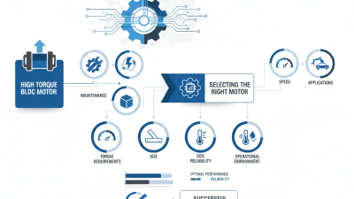
Start with the load, speed, and operating cycle. Calculate the required torque at the shaft, then include acceleration, friction, and mechanical losses. Do not select a motor using peak torque alone. Continuous torque matters more for conveyors, pumps, and repeated positioning systems. Check the torque-speed curve at your actual voltage.

My first instinct was to choose the largest motor. That approach can waste space, energy, and money. A smaller motor with suitable gearing may perform better. Still, the gearbox adds backlash and reduces efficiency. Measure carefully.

Review the rated voltage, phase current, thermal limits, and insulation class. Confirm whether the controller can handle startup current. Hall sensors or an encoder may be necessary for low-speed control and accurate positioning. For dusty or humid environments, inspect the enclosure rating and connector protection. Mounting space also matters. Leave room for airflow.

Test the motor under real conditions, not just on a workbench. Record temperature after a full duty cycle. Listen for vibration and check current at load. A motor that feels powerful for ten seconds may fail after an hour. That detail is easy to miss. Allow a safety margin, but avoid guessing. Reliable selection depends on measured load data and the manufacturer’s verified curves.