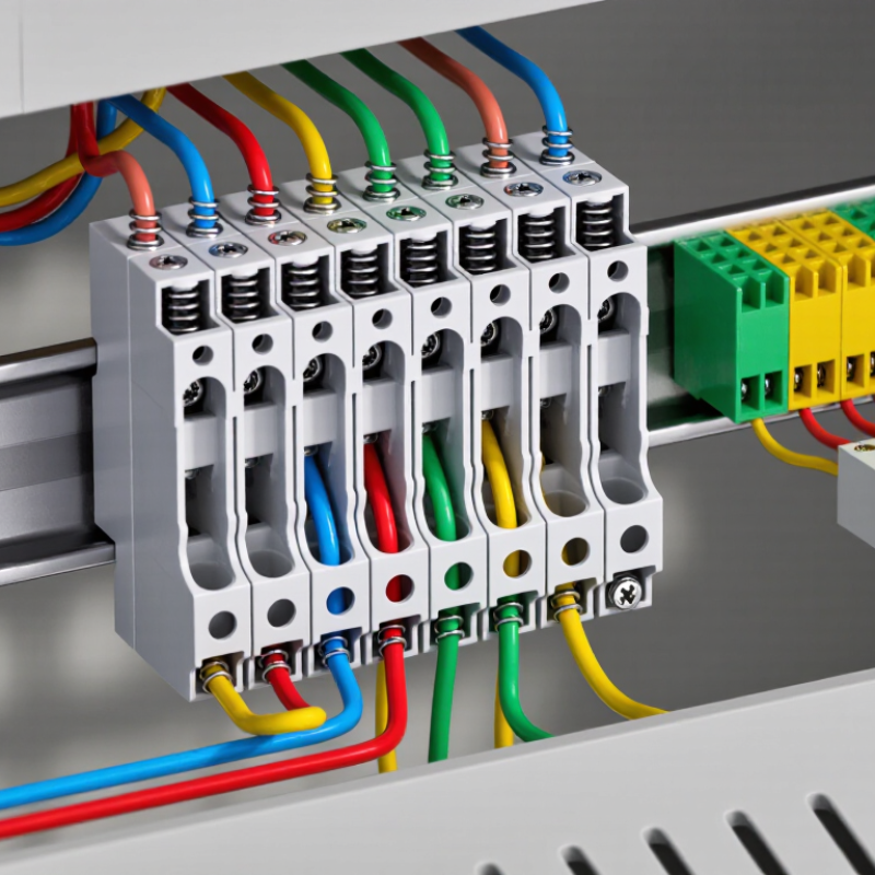
A Terminal Block is a practical electrical connector that joins wires securely without soldering. It usually contains an insulated body, metal terminals, and screws or spring clamps. Inside a control cabinet, it can connect a power supply to sensors, relays, motors, or other field devices. The arrangement looks simple. Its role is not.
Terminal blocks help technicians organize circuits, separate wiring functions, and simplify testing or maintenance. A labeled row can make a crowded cabinet easier to understand. For example, one section may carry 24-volt control signals, while another handles protective earth connections. Clear spacing and identification reduce the chance of connecting a wire to the wrong point. That small detail matters during commissioning.
Different designs serve different conditions. Feed-through blocks pass conductors from one side to another. Ground terminal blocks connect wiring to a mounting rail or grounding system. Fuse and disconnect versions add protection or isolation for specific circuits. Selection depends on wire size, current rating, voltage, temperature, vibration, and installation space. Manufacturer data should always be checked.
Real installations often reveal overlooked details. A screw may loosen under vibration. A stripped conductor may create heat. A poorly labeled terminal can delay fault finding for hours. Terminal blocks are not automatically safe simply because they are common. Correct stripping, tightening torque, insulation clearance, and inspection remain essential. Even experienced installers sometimes underestimate cabinet airflow or future expansion. That mistake deserves review.
Understanding what a Terminal Block is helps engineers and electricians design cleaner, more reliable connections. It also supports safer troubleshooting when equipment must be inspected or modified.
Under IEC 60947-7-1, a terminal block is a low-voltage electrical accessory designed to connect copper conductors securely. It provides an organized connection point between incoming cables, control circuits, and equipment wiring.
Many terminal blocks use screw clamps or spring-clamp mechanisms. They may also mount on a supporting rail inside a control cabinet.
The standard focuses on terminal blocks for copper conductors used in industrial and similar installations. It addresses practical safety requirements, including electrical insulation, temperature rise, mechanical strength, and resistance to abnormal heating. Markings such as rated voltage and current help engineers select a suitable device.
A terminal block is used to distribute power, join circuits, and simplify inspection or maintenance. For example, one side may receive a supply cable, while the other side connects to a motor starter or sensor.
Clear labels and separation plates can reduce wiring errors. Small details matter.
A conductor must be stripped correctly and inserted fully into the clamping area. Excessive tightening can damage the conductor, while insufficient tightening may create heat at the contact point.
IEC 60947-7-1 supports reliable design, but it cannot correct poor installation practices. Real projects also reveal a limitation: identical-looking blocks may have different ratings, spacing, or conductor ranges. Checking the technical marking and installation conditions remains essential.
What Is a Terminal Block and What Is It Used For?
A terminal block creates a controlled meeting point for electrical wires. Inside, a metal clamp or conductive bar carries current between connected conductors. An insulating body surrounds it and limits accidental contact. Barriers separate neighboring circuits. This structure makes wiring easier to inspect, replace, and test. In control panels, terminal blocks also organize power, signal, and grounding connections. A loose screw can still cause heat, voltage loss, or equipment failure.
The IEC 60947-7-1 standard covers important requirements for terminal blocks, including electrical performance and temperature behavior. The International Energy Agency’s Electricity 2024 report expects global electricity demand to grow by about 3.4% annually from 2024 to 2026. More electrical infrastructure increases the need for dependable, serviceable connections. However, a terminal block cannot correct damaged insulation or a badly prepared wire. Technicians should check conductor size, stripping length, tightening torque, and continuity. Vibration deserves attention too. Small errors become expensive faults.
Tips: Use the specified wire range. Keep copper fully inside the clamp. Mark each circuit clearly. Inspect for exposed strands. Do not rely on appearance alone; test the connection under suitable conditions. A useful, but imperfect, habit is retightening every screw routinely. Over-tightening can damage the conductor or housing, so measured torque is safer.
A terminal block joins and organizes electrical wires inside control panels, machines, and building systems. It provides a secure connection point without twisting wires together. In practice, I have found that clear labeling matters as much as the connection itself. A neat row of terminals makes testing faster and reduces wiring mistakes.
Feed-through terminal blocks connect one wire to another across a panel barrier. They suit power distribution and signal extension.
Ground terminal blocks bond protective conductors to the mounting rail or panel. Their metal connection helps direct fault current safely toward the grounding system.
Fuse terminal blocks add overcurrent protection in a compact space. They also make fuse replacement easier during maintenance.
Multi-level terminal blocks place two or more circuits vertically. This saves rail space, although crowded wiring can make inspection harder. I once chose a compact layout too quickly. It worked electrically, but access was poor.
Tips: Check the rated voltage, current, wire size, and temperature range before installation. Tighten each clamp to the specified torque. Loose connections can create heat and intermittent faults. Keep power and sensitive signal circuits separated when possible. Use ferrules only when the terminal design supports them. A small label on every circuit prevents expensive confusion later. Always verify the circuit is de-energized before touching conductors. Local electrical requirements may also affect grounding, fuse selection, and enclosure design.
A terminal block is an insulated connection point for joining and organizing electrical wires. It is commonly mounted inside control panels, junction boxes, and machinery. Each terminal holds a conductor securely, while a metal bridge carries current between connected wires. This arrangement makes inspection and maintenance easier.
In practical panel work, I check the terminal block’s markings before touching the wiring. A suitable voltage rating must meet or exceed the circuit voltage. The current rating must also handle the expected load without excessive heating. A rating is not a suggestion.
Wire size matters just as much. The terminal block must accept the conductor’s diameter, insulation type, and connection method. A loose wire can create resistance, heat, and eventual failure. Oversized wire may not fit correctly. Undersized wire may carry too much current.
Temperature also affects performance, so published ratings may require derating in crowded enclosures. UL 1059 compliance indicates that a terminal block has been evaluated against recognized requirements for construction and performance. However, compliance does not replace correct installation. The actual marking and certification details should be verified for the intended application.
Tips:
Compare voltage, current, wire-size, and temperature ratings together. Follow the specified tightening torque. Check every conductor after installation.
I once treated wire fit as the main concern, but spacing and heat were equally important. That mistake is easy to repeat. Leave enough room for bending, labeling, and future testing. Recheck the selection when the circuit load changes.
What Is a Terminal Block and What Is It Used For?
How to Select and Install Terminal Blocks for Industrial Systems
A terminal block connects field wiring to power, control, or grounding circuits inside an industrial panel. Selection should begin with voltage, current, conductor size, and fault conditions. The 2023 Terminal Blocks Market report by MarketsandMarkets estimated the market at about USD 3.5 billion, with growth driven by factory automation and safer wiring systems. That growth does not make every block suitable. A compact block may overheat when conductors are oversized or continuously loaded.
Check the rated voltage, current, insulation material, temperature range, and short-circuit rating. IEC 60947-7-1 provides a useful reference for low-voltage terminal blocks, while UL 1059 addresses North American requirements. Choose touch-safe designs for exposed service areas. Confirm that the wire ferrule, screwdriver, and conductor type match the manufacturer’s instructions. Small details matter.
Installation should follow the panel drawing, not memory. Mount blocks firmly on the correct rail, leave space for bending radius, and separate power circuits from sensitive signal wiring. Tighten every connection to the specified torque, then record the value. A loose screw can create heat, discoloration, and intermittent faults. In practice, rushed labeling remains a common weakness. Use durable markers on both wire ends. Inspect after energizing, using thermal scanning when the system carries a meaningful load. One mistake deserves attention: “tight enough” is not a measurement. Recheck torque after maintenance or vibration exposure.
| Terminal Block Type | Primary Function | Typical Industrial Applications | Common Conductor Arrangement | Typical Rated Voltage Range | Typical Rated Current Range | Key Selection Considerations | Installation Requirements |
|---|---|---|---|---|---|---|---|
| Feed-through | Joins one incoming conductor to one outgoing conductor while maintaining electrical continuity. | Control cabinets, machine wiring, motor control panels, power distribution, and field-device connections. | Single circuit; one conductor on each side of the terminal. | Typically 300–1,000 V AC/DC | Typically 10–150 A | Conductor cross-section, current load, insulation clearance, short-circuit requirements, and mounting method. | Install on a compatible DIN rail or mounting surface. Tighten the clamp to the specified torque and verify conductor insertion. |
| Grounding / Protective Earth | Connects protective conductors to the grounding system and bonds them to the mounting rail or grounding bar. | Industrial control panels, automation cabinets, distribution boards, and equipment grounding networks. | One or more protective conductors connected to a conductive grounding path. | Typically 300–1,000 V AC/DC | Depends on conductor size and short-circuit withstand rating | Grounding standard, fault-current capacity, rail material, corrosion resistance, and reliable metal-to-metal contact. | Use only on an approved conductive rail or grounding system. Remove paint or coatings where required and confirm continuity with a meter. |
| Fused | Provides circuit termination and overcurrent protection in the same terminal assembly. | Sensor circuits, control circuits, instrumentation, lighting branches, and low-power protection circuits. | Single circuit with an integrated replaceable fuse. | Typically 250–800 V AC/DC | Typically 1–30 A | Fuse type, interrupting rating, voltage rating, heat dissipation, spare-fuse storage, and replacement access. | Install the correct fuse rating and type. Confirm that the circuit is de-energized before replacing the fuse. |
| Disconnect / Isolation | Allows a circuit to be opened for testing, maintenance, or safe isolation without removing the wiring. | Instrumentation loops, control circuits, maintenance panels, and equipment isolation points. | Single circuit with a lever, knife disconnect, plug, or removable link. | Typically 300–1,000 V AC/DC | Typically 5–100 A | Isolation method, visible switching position, load type, switching frequency, and applicable safety procedures. | Provide clear circuit identification and leave enough space for safe operation of the disconnect mechanism. |
| Double-Level | Terminates two independent circuits in a vertical arrangement to reduce control-panel width. | PLC panels, relay cabinets, compact automation systems, and high-density control wiring. | Two electrically separate levels in one terminal body. | Typically 300–800 V AC/DC | Typically 5–32 A per level | Available wiring space, screwdriver access, heat dissipation, circuit identification, and required accessories. | Confirm that both levels remain accessible after wiring. Use markers or labels to prevent cross-connection. |
| Multi-Level | Combines three or more independent circuits in a vertically stacked terminal assembly. | High-density PLC I/O, process-control cabinets, building automation, and signal distribution. | Three or more electrically isolated levels. | Typically 150–800 V AC/DC | Typically 2.5–32 A per level | Clearance between levels, heat buildup, wire routing, test access, and terminal-marker visibility. | Route wires to avoid blocking adjacent levels. Follow the manufacturer’s specified strip length and torque values. |
| Distribution / Power Distribution | Splits one incoming supply into multiple outgoing circuits. | Power distribution panels, machine tools, HVAC controls, industrial lighting, and auxiliary supply circuits. | One common input with multiple electrically connected outputs. | Typically 300–1,000 V AC/DC | Typically 25–250 A | Input-to-output current balance, busbar capacity, conductor size, temperature rise, and touch protection. | Secure the incoming conductor first, then connect outgoing circuits. Verify that all connected conductors are rated for the distribution current. |
| Sensor / Instrumentation | Terminates low-level signals and may provide testing, shielding, or signal-conditioning functions. | Temperature transmitters, pressure sensors, proximity sensors, process instrumentation, and analog I/O. | Usually one signal pair, three-wire, or four-wire circuit. | Typically 50–300 V AC/DC | Typically 1–10 A | Signal integrity, shielding, noise immunity, loop resistance, terminal spacing, and compatibility with small conductors. | Separate low-level signal wiring from high-power wiring. Connect cable shields according to the system grounding design. |
| Spring-Clamp | Uses spring pressure to maintain conductor contact and resist loosening caused by vibration or thermal cycling. | Rail vehicles, industrial machinery, robotics, process equipment, and vibration-prone control cabinets. | Single-level or multi-level feed-through arrangement. | Typically 300–1,000 V AC/DC | Typically 5–100 A | Conductor type, wire ferrule requirements, vibration level, insertion tool, and temperature range. | Strip the conductor to the specified length and insert it fully. Check that the spring clamp has captured the conductor securely. |
| Screw-Clamp | Uses a screw-operated clamp to secure solid, stranded, or ferruled conductors. | General-purpose control panels, power panels, machine wiring, and fixed industrial installations. | Single-level, multi-level, or barrier-style arrangement. | Typically 300–1,000 V AC/DC | Typically 5–150 A | Required tightening torque, vibration exposure, conductor type, maintenance access, and periodic inspection needs. | Use a calibrated torque screwdriver where specified. Avoid over-tightening, under-tightening, and placing insulation under the clamp. |
| Barrier / High-Voltage | Provides increased separation between adjacent circuits to reduce the risk of accidental contact and arcing. | Motor starters, power supplies, industrial heaters, drives, and higher-voltage control assemblies. | Individual circuits separated by insulating barriers. | Typically 600–1,000 V AC/DC | Typically 10–150 A | Required creepage and clearance, pollution degree, overvoltage category, enclosure rating, and insulation material. | Maintain the specified spacing and install end plates or covers where required. Do not remove barriers from energized equipment. |
| Pluggable | Allows a wired terminal section to be disconnected from its fixed base for faster equipment replacement or maintenance. | Modular control systems, removable machine modules, test equipment, and serviceable automation panels. | Plug-and-socket connection between a fixed base and removable terminal section. | Typically 150–600 V AC/DC | Typically 2.5–40 A | Number of mating cycles, locking mechanism, coding, vibration resistance, and accidental disconnection protection. | De-energize before unplugging unless the assembly is specifically rated for live disconnection. Engage locks fully after reconnection. |
| Selection Checklist | Confirms that the selected terminal block is electrically, mechanically, and environmentally suitable. | Applicable to all industrial control, power, and instrumentation installations. | Based on the complete circuit and enclosure design. | Select a rating equal to or greater than the system requirement | Select a rating equal to or greater than the continuous load, with applicable derating |
| Review the technical documentation, calculate temperature rise where necessary, and verify compatibility with the enclosure and wiring system. |
| Installation Sequence | Provides a safe and repeatable method for installing terminal blocks in an industrial system. | Control cabinets, distribution boards, machine panels, and field junction boxes. | Arranged according to the electrical schematic and panel layout. | Verify against the terminal and system ratings | Verify against conductor capacity, protective-device rating, and terminal rating |
| Perform continuity, insulation, polarity, grounding, and functional tests before energizing the system. Recheck labels and torque records during commissioning. |