How to Choose the Best Frameless Motor for Your Application

Choosing the right Frameless Motor begins with understanding the motion system, not the catalog alone. A frameless motor integrates directly into your machine, so its performance depends on the surrounding mechanics. Torque, speed, duty cycle, available space, and thermal conditions must be evaluated together. That sounds simple. Real applications rarely behave so neatly.

An actuator moving a surgical instrument may need quiet operation, precise feedback, and strict cleanliness. A robotic joint may require high peak torque, low cogging, and repeated acceleration. A compact gimbal may prioritize low inertia over continuous power. These differences change the best motor choice. This guide examines torque requirements, winding options, cooling methods, resolver or encoder compatibility, and installation tolerances. It also considers the motor’s real operating temperature, not only its impressive laboratory rating. A promising specification can still fail inside a crowded housing.

Reliable selection requires evidence. Review manufacturer datasheets, test conditions, efficiency curves, and thermal limits carefully. Ask how ratings were measured. Confirm whether the stated torque applies continuously or only for short periods. Engineers should also check bearing support, rotor retention, cable routing, and service expectations. Small oversights become expensive redesigns. No selection method removes every uncertainty. Prototype testing remains essential, especially when friction, vibration, or imperfect alignment affects performance. The best Frameless Motor is not always the largest or fastest option. It is the one that delivers controlled motion, manageable heat, and dependable life within the complete application.
How to Choose the Best Frameless Motor for Your Application

Define the Application’s Motion, Load, and Environmental Requirements

How to Choose the Best Frameless Motor for Your Application

When selecting a frameless motor, define the motion before comparing torque charts. Is the axis rotating continuously, indexing between positions, or accelerating a moving load? Record the required speed, acceleration, travel profile, and positioning accuracy. A short, sharp move may demand more peak torque than a slower cycle. Do not rely on average torque alone.

Calculate the load inertia, friction, gravity effects, and transmission ratio. Include the rotor, coupling, gearbox, and attached mechanism. The motor must handle continuous torque during normal operation and peak torque during acceleration or disturbance. I have seen designs pass a spreadsheet check but overheat during real cycling. The missing detail was often duty cycle. Test the complete motion profile when possible. Real behavior is rarely perfect.

Environment changes the selection. Check ambient temperature, available cooling, dust, moisture, vibration, and installation space. A compact frameless motor may fit mechanically but lose torque when heat cannot escape. Review winding temperature limits, insulation requirements, feedback compatibility, and cable routing before finalizing the design. For clean or vacuum applications, material choices and outgassing limits may matter. Ask how the motor will be mounted, not only how it will be powered. Small alignment errors can create unwanted bearing loads and noise. Leave reasonable thermal and torque margins. Oversizing everything is not always wise; it can increase cost, inertia, and control difficulty.

Compare Frameless Motor Types, Torque Ratings, and Speed Ranges

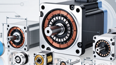
Choosing the best frameless motor starts with comparing motor construction, torque ratings, and speed requirements. Iron-core motors usually deliver strong continuous torque and efficient heat transfer. They suit robotic joints, actuators, and other demanding loads. Coreless or slotless designs reduce cogging and provide smoother motion. They can perform well in precision instruments, but their heat capacity may be lower.

Do not select a motor from peak torque alone. Compare continuous torque, peak torque, and the duration of each load. A joint lifting a 5-kilogram arm needs different performance from a spindle reaching 10,000 revolutions per minute. Check the full speed range, torque drop at high speed, winding temperature, and available cooling. I have found that real measurements often differ from catalog estimates. Mounting stiffness, friction, and control settings can change the result.

Tips: Create a simple load profile before choosing. Record startup torque, average torque, peak duration, and target speed. Leave thermal and torque headroom. More is not always better. A motor rated far above the application may add cost, inertia, and control difficulty. Test the motor with the actual gearbox, shaft, and feedback sensor when possible. This step can reveal vibration or heating that calculations miss.
How to Choose the Best Frameless Motor for Your Application - Compare Frameless Motor Types, Torque Ratings, and Speed Ranges
Frameless Motor Type Typical Continuous Torque Typical Peak Torque Typical Speed Range Torque Density Rotor Inertia Key Advantages Common Applications Selection Considerations
Frameless BLDC Motor 0.02–2 N·m 0.05–6 N·m 3,000–20,000 rpm Medium to high Low Compact construction, efficient electronic commutation, broad operating-speed capability, and relatively simple integration. Compact actuators, laboratory equipment, camera mechanisms, pumps, fans, and lightweight robotic joints. Choose this type when high speed, low moving mass, and compact packaging are more important than maximum low-speed torque.
Frameless Permanent-Magnet Servo Motor 0.1–10 N·m 0.3–30 N·m 500–10,000 rpm High Low to medium High positioning accuracy, strong overload capability, good dynamic response, and compatibility with closed-loop control. Robotic joints, precision automation, semiconductor equipment, medical mechanisms, and multi-axis motion systems. Verify encoder compatibility, thermal limits, peak-duty duration, commutation method, and the required continuous torque at the actual operating speed.
Iron-Core Frameless Torque Motor 0.5–100 N·m 1.5–300 N·m 50–5,000 rpm Very high Medium to high High torque per active volume, strong overload capacity, and effective heat transfer through the iron core. Rotary tables, direct-drive axes, industrial robots, machine tools, and high-load positioning systems. Use when high torque is required without a gearbox. Consider cogging torque, magnetic attraction, bearing load, and the resulting effect on precision.
Ironless Frameless Motor 0.01–2 N·m 0.03–5 N·m 1,000–10,000 rpm Medium Very low Very low cogging torque, smooth motion, low rotor inertia, and excellent small-signal responsiveness. Precision scanners, optical equipment, low-friction positioning systems, gimbals, and delicate motion platforms. Choose this type for smooth low-speed motion and rapid acceleration. Provide careful mechanical support because the magnetic circuit may generate lower inherent structural stiffness.
High-Torque Low-Speed Frameless Motor 5–150 N·m 15–450 N·m 1–1,000 rpm Very high High Direct-drive operation, high continuous torque, reduced backlash, and elimination of gearbox wear and maintenance. Large rotary joints, robotic arms, indexing tables, pan-and-tilt systems, and heavy positioning axes. Match the motor to the continuous load torque, acceleration torque, duty cycle, thermal path, and maximum allowable radial and axial bearing loads.
Frameless Gimbal Motor 0.02–1.5 N·m 0.05–4 N·m 100–6,000 rpm Medium Very low Low inertia, smooth bidirectional response, compact packaging, and suitability for frequent reversals and stabilization control. Camera gimbals, antenna positioning, optical stabilization, lightweight pointing systems, and inspection equipment. Prioritize low torque ripple, low bearing friction, fast current-loop response, and accurate position feedback rather than only maximum speed.
Important: The values shown are representative engineering ranges for comparison, not guaranteed ratings for every design. Actual torque and speed depend on motor diameter and length, winding, bus voltage, controller limits, cooling method, duty cycle, bearing arrangement, ambient temperature, and allowable temperature rise. Always size the motor using continuous torque, peak torque, acceleration requirements, operating speed, and thermal conditions at the same time.

Evaluate Thermal Performance, Efficiency, and Continuous Duty Limits

How to Choose the Best Frameless Motor for Your Application

Evaluate Thermal Performance, Efficiency, and Continuous Duty Limits

Thermal performance often determines whether a frameless motor succeeds in real equipment. Start with the winding temperature, not only the published torque. Measure current, ambient temperature, and housing temperature during a realistic load cycle. A motor may deliver impressive peak torque for several seconds, yet overheat during continuous operation. Check the thermal resistance path through the stator, housing, bearings, and cooling structure. Small mounting gaps can behave like unwanted insulation.

Efficiency also affects system temperature. Lower electrical losses mean less heat inside the winding. Compare copper loss, iron loss, inverter loss, and mechanical friction at the actual operating speed. Do not judge efficiency at one convenient test point. Continuous duty, often identified as S1 duty, requires stable operation at the rated load until temperatures stop rising. Review the manufacturer’s test conditions carefully. Different cooling methods make direct comparisons unreliable.

Tips: Use a temperature sensor near the winding. Test the motor inside its final housing. Record temperatures every few minutes. Leave a safety margin.

A spreadsheet helps, but it cannot replace testing. A theoretically suitable motor may perform poorly after assembly. Recheck the design when airflow, preload, or controller settings change. Thermal limits are not merely numbers; they shape reliability, service life, and safe operating decisions.

Match the Motor with Compatible Feedback and Control Systems

Choosing a frameless motor starts with the feedback and control system, not only torque and speed. A motor may fit the mechanical envelope yet perform poorly with an incompatible encoder. Check the encoder type, signal voltage, resolution, and communication interface before ordering. Confirm whether the controller supports incremental, absolute, or resolver feedback.

Feedback quality shapes motion accuracy. In a robotic joint, a high-resolution encoder can reveal tiny position changes near zero speed. However, excessive resolution may increase data load and tuning demands. Match the feedback bandwidth with the controller’s sampling rate. Also verify commutation feedback, especially when the motor requires precise electrical alignment. Small timing errors can cause vibration, heat, or audible noise.

Thermal feedback deserves equal attention. A winding sensor can protect the motor, but only if the controller reads its resistance range correctly. Review current limits, regeneration handling, grounding, and cable shielding together. During bench testing, watch the position error, current ripple, and housing temperature. A quiet motor is not always a well-tuned motor. I once treated stable speed as proof of compatibility, but low-speed positioning later exposed a feedback delay. That mistake was avoidable. Leave room for filtering, calibration, and imperfect installation conditions. A practical match is one that remains predictable after real cables, real loads, and real heat enter the system.

How to Choose the Best Frameless Motor for Your Application

Match the motor with a compatible feedback device and control system. The chart shows typical minimum feedback resolutions used for common control modes; higher-resolution feedback supports tighter position accuracy and smoother motion.

These values are practical engineering starting points. The final feedback resolution should be selected according to load inertia, speed, accuracy, bandwidth, commutation method, and the capabilities of the motor controller.

Verify Integration, Reliability, Cost, and Long-Term Service Needs

How to Choose the Best Frameless Motor for Your Application

A frameless motor is not a drop-in component. Integration must be checked at the drawing stage. Confirm rotor inertia, air gap, axial loading, mounting tolerances, and encoder alignment. A few tenths of a millimeter can affect noise, heat, and service life. Thermal paths deserve equal attention. The stator needs a defined route into the machine frame, not only a convenient mounting surface. Test the complete assembly under real duty cycles.

Reliability depends on more than rated torque. Review continuous and peak loads, winding temperature, bearing arrangements, sealing, and cable strain relief. IEC 60034 testing provides useful performance references, but application testing remains essential. The U.S. Department of Energy reports that motor-driven equipment consumes more than half of industrial electricity. Small efficiency losses can therefore become large operating costs. The International Energy Agency has estimated that electric motor systems use roughly 43–46% of global electricity. Efficiency is not a decorative specification.

Purchase price can hide integration labor, custom tooling, controls, cooling, and replacement inventory. Ask for thermal curves, tolerance data, test methods, and realistic service intervals. A supplier should explain how the rotor can be removed without damaging nearby components. Long-term support also requires documented revisions and available technical assistance. In prototype reviews, engineers sometimes select the highest torque option too early. That choice may increase mass, heat, and cost unnecessarily. The spreadsheet can still lie. Check the machine.