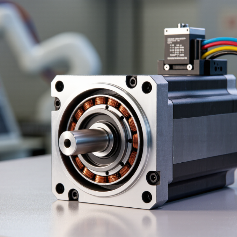
A Brushless Servo Motor combines electromagnetic force with continuous position feedback. Unlike a brushed motor, it uses electronic commutation instead of physical brushes. This design reduces contact wear, electrical noise, and maintenance around the rotating shaft. Inside the motor, permanent magnets rotate near a carefully wound stator. An encoder reports the shaft’s position to the drive. The drive then adjusts current within milliseconds.
Dr. R. Krishnan, a respected motor-drive researcher, emphasizes this relationship: “A servo system is more than a motor; it is a complete motion-control system.” That principle matters in real equipment. A robotic joint, CNC axis, or packaging machine needs more than rotation. It needs accurate speed, controlled torque, and repeatable stopping. A small encoder error can leave a machine arm slightly misaligned. Poor tuning can create vibration, overshoot, or a sharp mechanical hum.
The working process is precise, but not mysterious. Sensors measure position and speed. A controller compares those values with the commanded motion. The amplifier changes phase current and torque. This loop repeats continuously. Fast response is the goal.
Still, simplified explanations can mislead. A high-quality Brushless Servo Motor cannot correct every mechanical problem. Excessive load, loose couplings, heat, or incorrect inertia settings can reduce accuracy. Engineers must match the motor, drive, encoder, and application. That selection process requires practical testing, not only catalog reading. This article examines the motor’s structure, control loop, benefits, limits, and common industrial uses.
What Is a Brushless Servo Motor and How Does It Work?
A brushless servo motor is a closed-loop motor designed for accurate position, speed, and torque control. Unlike brushed motors, it uses electronic commutation instead of mechanical brushes. Its three-phase construction includes three stator winding groups, spaced 120 electrical degrees apart. A permanent-magnet rotor turns inside these windings. When the drive energizes each phase in sequence, the magnetic field rotates and pulls the rotor forward.
The servo drive receives feedback from an encoder or resolver mounted near the shaft. This feedback shows the rotor’s exact position and speed. The controller then adjusts current several thousand times per second, depending on the application. In a packaging machine, for example, the shaft may stop within a fraction of a degree while moving a belt or cutting tool. That is the practical advantage: controlled motion, not simple rotation.
The International Energy Agency reports that electric motor systems consume roughly 45% of global electricity. The U.S. Department of Energy also estimates that motor-driven equipment uses about 70% of industrial electricity in the United States. Efficient control matters. However, efficiency figures can mislead when they ignore the drive, gearbox, cooling, and load profile. A motor may reach high efficiency at rated speed but perform poorly during repeated acceleration. That detail is easy to miss. Field testing remains important, especially when vibration, heat, and positioning errors appear together.
Brushless servo motors use electronically controlled currents in three stator phases to create a rotating magnetic field. This illustrative chart shows balanced sinusoidal phase currents, each separated by 120 electrical degrees, with a peak current of 10 A.
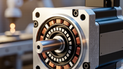
A brushless servo motor creates torque through controlled stator currents and permanent rotor magnets. Copper windings sit in the stationary stator. An inverter sends three-phase current through these windings. The currents create a rotating magnetic field. Rotor magnets chase this field, producing continuous shaft torque.
The controller changes current timing according to rotor position. An encoder or resolver supplies this position feedback. The drive then adjusts the phase angle and current magnitude within milliseconds. The q-axis current mainly produces torque, while d-axis current influences magnetic flux. More q-axis current usually means more torque, until thermal or magnetic limits appear.
The U.S. Department of Energy notes that motor-driven equipment consumes more than half of industrial electricity in the United States. The IEA’s Energy Efficiency 2023 analysis also identifies electric motors as responsible for roughly half of global electricity use. Small efficiency gains matter.
The idealized explanation is incomplete. Friction, winding resistance, inverter losses, cogging, and encoder error affect real performance. During commissioning, poor current-loop tuning can create audible vibration and position overshoot. That detail is easy to underestimate.
Tips: Select a motor with suitable continuous and peak torque ratings. Check RMS current, not only the advertised peak value. Keep encoder cables separated from power cables. Confirm thermal performance at the actual duty cycle. When precision matters, measure shaft temperature and following error under load.
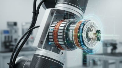
A brushless servo motor uses permanent magnets and electronic commutation instead of mechanical brushes. Its encoder feedback is the critical guide. The encoder reports shaft position, often thousands of times per revolution, to the drive controller. The controller compares the commanded position with the measured position, then corrects the error through current and voltage changes.
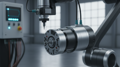
Position control is the outer loop. Speed control sits inside it, while torque control responds fastest through motor current. If a robotic joint must stop at 90 degrees, the encoder detects even a small overshoot. The drive then reduces current and reverses torque briefly. This happens within milliseconds. The response feels smooth, but it is not automatic perfection. Poor tuning can create vibration, audible whining, or a warm motor housing.
The International Federation of Robotics reported 541,302 industrial robot installations worldwide in 2023. That growth increases demand for accurate feedback in compact motion systems. The International Energy Agency has also reported that motor-driven systems consume roughly 46% of global electricity, making efficient control valuable beyond precision alone. In field commissioning, technicians should verify encoder alignment, cable shielding, sampling settings, and load inertia. One overlooked detail matters. A loose coupling can make excellent feedback look unreliable. Encoder resolution improves measurement, but it cannot compensate for backlash, mechanical flex, or an incorrectly tuned control loop.
| Technical Dimension | Typical Data or Operating Principle | How It Works in a Brushless Servo System | Control Relevance | Practical Notes |
|---|---|---|---|---|
| Motor Construction | Permanent-magnet rotor and three-phase stator windings | The rotor magnets interact with the rotating magnetic field generated by the stator phases. | Produces continuous electromagnetic torque without mechanical commutator contacts. | The motor is commonly classified as a permanent-magnet synchronous motor when operated with electronic commutation. |
| Electronic Commutation | Inverter switches current through three motor phases | A servo drive changes the phase currents according to the estimated or measured rotor electrical angle. | Maintains the correct torque-producing field orientation as the rotor turns. | Field-oriented control can regulate torque-producing and flux-producing current components independently. |
| Rotor Position Feedback | Incremental encoder, absolute encoder, resolver, or Hall sensors | The feedback device reports rotor position to the servo drive. | Enables accurate commutation, position control, speed estimation, and error detection. | Encoders generally provide finer motion information than Hall sensors, while absolute devices can retain position information after power-up. |
| Encoder Resolution | Specified in counts per revolution or bits per revolution | An incremental encoder may provide pulses per revolution, while an absolute encoder reports a digital position value. | Higher resolution reduces quantization in position measurement and improves low-speed control. | The usable mechanical resolution depends on encoder specification, signal processing, interpolation, installation accuracy, and mechanical compliance. |
| Position Measurement | Mechanical shaft angle measured relative to a reference position | The controller compares commanded position with measured position and calculates the position error. | Position error is used to generate a speed command in the outer control loop. | A homing routine may be required for incremental feedback systems after power is removed. |
| Speed Measurement | Calculated from encoder position change over time | The drive differentiates or estimates position feedback to determine actual shaft speed. | The speed loop adjusts torque-producing current to reduce the difference between commanded and measured speed. | Filtering improves noise performance but introduces delay, so the filter must be selected carefully. |
| Torque Production | Approximately proportional to torque-producing current | The inverter regulates phase current so the stator magnetic field remains correctly aligned with the rotor field. | Current control provides rapid torque response and limits motor heating. | The exact torque constant depends on motor design, current definition, magnetic saturation, temperature, and operating point. |
| Control Structure | Nested loops: current, speed, and position | The inner current loop responds fastest; the speed loop operates around it; the position loop is normally the outer loop. | Nested bandwidths allow fast torque response while maintaining stable position regulation. | A common design approach is to tune the current loop first, followed by the speed loop and then the position loop. |
| Current Loop | Regulates phase or d-q axis current | The controller compares measured current with the current command and adjusts inverter voltage. | Controls electromagnetic torque and supports fast disturbance rejection. | Current sensors and inverter switching characteristics strongly influence current-loop accuracy. |
| Speed Loop | Compares commanded speed with measured speed | A proportional-integral controller commonly generates a torque or current command from speed error. | Maintains speed under changing load torque and compensates for moderate disturbances. | Excessive gain can cause vibration, overshoot, or acoustic noise, especially in systems with flexible couplings. |
| Position Loop | Compares target position with encoder position | The position controller produces a speed command based on position error and motion-profile limits. | Determines final positioning accuracy, settling behavior, and tracking performance. | Acceleration, velocity, and jerk limits help reduce mechanical shock and following error. |
| Position Accuracy | Depends on encoder resolution, calibration, mechanics, and tuning | The feedback loop corrects position error, but it cannot eliminate errors caused by backlash, torsional flexibility, or structural deflection. | Defines the achievable repeatability and absolute accuracy of the complete motion axis. | Encoder accuracy and system repeatability are different specifications and should be evaluated separately. |
| Speed Range | From near-zero controlled motion to the motor's rated maximum speed | Feedback allows the drive to maintain speed even when load conditions change. | Closed-loop regulation improves low-speed stability and dynamic response compared with open-loop operation. | The usable speed range is limited by motor voltage, winding characteristics, load inertia, cooling, and feedback quality. |
| Torque-Speed Relationship | Constant-torque region followed by a voltage-limited region | At lower speeds, the drive can generally maintain rated current; at higher speeds, available torque may decrease as back electromotive force rises. | Determines acceleration capability, continuous load capacity, and peak performance. | The continuous torque rating is thermally limited, while peak torque is usually limited by current, magnets, and short-term heating. |
| Back Electromotive Force | Voltage generated by rotor motion in the stator windings | Back electromotive force increases approximately with motor speed and opposes the applied voltage. | Reduces the voltage headroom available for current regulation at high speed. | The waveform may be sinusoidal or trapezoidal, depending on motor and commutation design. |
| Electrical Efficiency | Influenced by copper loss, iron loss, inverter loss, and mechanical friction | The drive controls current and commutation to convert electrical power into mechanical output efficiently. | Efficiency affects thermal design, energy consumption, and continuous operating capability. | Efficiency changes with speed, torque, switching frequency, temperature, and load duty cycle. |
| Thermal Management | Natural convection, forced-air cooling, or machine-frame cooling | Heat generated by winding resistance and other losses must be transferred away from the motor and drive. | Limits continuous torque and prevents insulation or magnet temperature from exceeding safe levels. | Thermal sensors may be installed in the windings or motor housing for protection and monitoring. |
| Following Error | Difference between commanded trajectory and measured position | The controller monitors position deviation during acceleration, deceleration, and load changes. | Excessive following error can trigger a protective fault or indicate inadequate tuning or mechanical overload. | Common causes include insufficient torque, excessive acceleration, backlash, resonance, encoder problems, or incorrect scaling. |
| Regenerative Braking | Mechanical energy is converted back into electrical energy during deceleration | The motor operates as a generator and returns energy to the DC bus of the drive. | Controls deceleration while potentially increasing DC-bus voltage. | A regenerative resistor or suitable energy-management circuit may be required when returned energy exceeds the system's absorption capacity. |
| Typical Applications | Robotics, CNC axes, packaging, semiconductor equipment, and automated assembly | These applications require coordinated motion, repeatable positioning, and rapid response to changing loads. | Encoder feedback supports synchronized motion and reliable fault detection. | The appropriate motor and feedback device should be selected according to load inertia, duty cycle, accuracy, speed, and environmental conditions. |

A brushless servo motor replaces mechanical brushes with timed electronic switching. In six-step commutation, the drive changes the current path every 60 electrical degrees. Each change energizes two motor phases; the third phase is usually left floating. Six switching states complete one electrical cycle. That cycle is not necessarily one rotor revolution: pole pairs determine how many electrical cycles occur per mechanical turn.
Hall sensors can indicate rotor position, while some drives estimate it from phase voltages. The controller uses that position to select the next switching state. Picture a rotor magnet passing a stator tooth: the drive advances the current pattern at each 60-degree boundary, pulling the rotor onward. The timing matters. Late switching can weaken torque; early switching can raise current and heat. Not perfectly smooth. Six-step control can produce torque ripple, especially at low speeds, so careful tuning and suitable feedback matter.
The U.S. Department of Energy’s 2014 report on motor-driven systems estimates that these systems use about 69% of electricity in U.S. manufacturing. That figure covers many motor types, not servo motors alone, but it shows why drive efficiency matters. IEC 61800-9-2 provides efficiency indicators for adjustable-speed drive systems, offering a useful framework for evaluating drive losses. In practice, a six-step drive is relatively simple, but its abrupt phase changes may create audible vibration. The best choice depends on load, speed range, and acceptable ripple—not just switching frequency.
What Is a Brushless Servo Motor and How Does It Work?
A brushless servo motor combines electronic commutation, permanent magnets, and closed-loop feedback. Unlike brushed motors, it has no mechanical brushes rubbing against a commutator. This design reduces wear and supports precise, quiet motion. The motor controller changes current timing according to rotor position. An encoder supplies that position continuously.
Encoder resolution is a major part of servo performance. A 20-bit encoder represents 1,048,576 positions per revolution. That equals roughly 0.000344 degrees per count. Very fine measurement. During commissioning, this resolution helps the controller detect small position errors and correct them quickly. A shaft moving only a fraction of a degree can still produce measurable feedback.
However, resolution is not the same as absolute accuracy. Bearing play, shaft vibration, electrical noise, temperature changes, and imperfect calibration can reduce real-world precision. I have seen systems with excellent encoder specifications behave poorly after loose couplings were installed. The feedback was detailed, but the mechanics were not stable. This is an important limitation to examine. Control-loop tuning also matters, because aggressive settings may create vibration instead of useful accuracy. A reliable design therefore evaluates the encoder, motor, drive, coupling, and load as one system.